Refer to the exhibit.

A user connects a device to GigabitEthernet 1/0/1 on switch. The device does not have an
802.1X supplicant. One minute passes. How does the switch port handle the client?
- A. It blocks the client
- B. It assigns the client to VLAN2
- C. It assigns the client to VLAN3
- D. It assigns the client to VLAN4
Answer : D
Explanation: VLAN4 is configured to be a guest vlan.
Reference:ProCurve Network Security solutions,Guest VLANs: the interim solution http://www.hp.com/rnd/pdf_html/guest_vlan_paper.htm#interim_solution
A company has configured two switches as an HP Intelligent Resilient Framework (IRF) virtual device. The IRF port on each switch is bound to multiple physical links. How does the switch select the link for transmitting packets on that IRF port?
- A. It uses a round-robin mechanism in which it sends each packet over a different link in turn.
- B. It uses a weighted round-robin mechanism, in which it sends each packet over a different link in turn, but can send more packets over certain links over higher weighted.
- C. It uses one of the links as an active link, the other links are in standby mode and can become active if the active link fails
- D. It uses a hash of various Layer 2, 3, or 4 information in the packet, depending on the type of traffic, the switch model, and the IRF load-sharing.
Answer : C
Explanation: IRF provides both link and node redundancy.
Reference:https://en.wikipedia.org/wiki/Intelligent_Resilient_Framework
Refer to the exhibit.


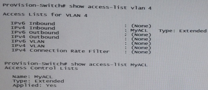
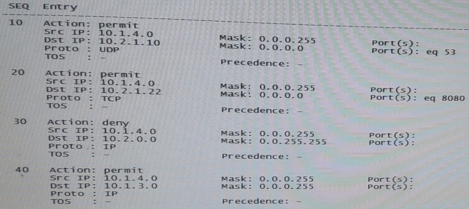
The switch with the ACL shown in the exhibit has IP address 10.1.4/24 on VLAN 4. It is the default router for 10.1.0/24. A client in VLAN 4 broadcast a DHCP discovery request, and the request arrives on this switch.
What happens?
- A. The ACL processes the packet, and the packet is permitted and then switched.
- B. The switch routes the packet out of VLAN 4 to the VLAN with the DHCP server.
- C. The ACL processes the packet, and the packet is dropped.
- D. The switch floods the broadcast in VLAN 4.
Answer : D
Refer to the exhibit.

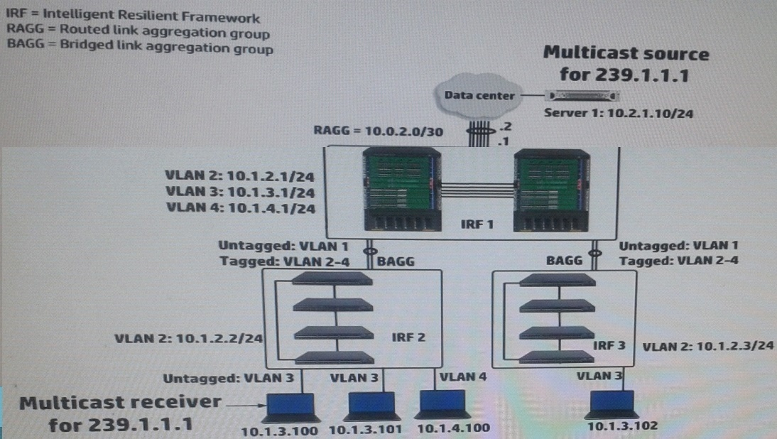
IRF 1, at the campus core campus core, enables Internet Group Management Protocol
(IGMP) on its VLAN3 interface. IRF 1 is also part of a multicast routing solution with the data center infrastructure devices. How can a network administrator ensure that only endpoints that have registered for multicasts destined to 239.1.1.1 receive these multicasts?
- A. On every campus IRF virtual switch, set VLAN 3 as the multicast VLAN
- B. On IRF 1, enable IGMP snooping on VLAN3
- C. On each access layer IRF virtual switch, enable IGMP snooping on VLAN 3
- D. On each access layer IRF virtual switch, create a Layer 3 interface VLAN3. Enable IGMP on that interface
Answer : C
Explanation: IGMP snooping enables Layer 2 switches to establish a Layer 2 multicast forwarding table instead of flooding all multicast packets. To populate the Layer 2 multicast forwarding table, IGMP snooping listens to IGMP messages exchanged between a Layer 3 multicast device and hosts.
Reference: 07-IP Multicast Configuration Guide, 02-IGMP snooping configuration http://www.h3c.com/portal/Technical_Support___Documents/Technical_Documents/Switch es/H3C_S12500_Series_Switches/Configuration/Operation_Manual/H3C_S12500_CG-
Release7128-6W710/07/201301/772657_1285_0.htm
A company needs a simple authenticate solution for guests. The HP Comware access layer switches will implement portal authentication (or Web-Auth). The network administrator wants the switch to host the login web page on an IP address that not used for any other purpose.
What should the administrator do to accomplish this goal?
- A. Set the IP address when defining the local portal server, and create a loopback interface for the address
- B. Create RADIUS scheme that specifies this IP address for the authentication server. Select this scheme for portal authentication in the default domain
- C. Create a layer 3 interface for the guest VLAN and assign the desired IP address. Activate local portal authentication on this interface.
- D. Set the IP address when defining the local portal server, and the switch automatically begins using that address.
Answer : C
Explanation: *Enable portal server on Onboarding VLAN Interface, this will activate the default Portal ACL (deny all, redirect tcp port 80 to TCP-Cheat)
[comware5]interface Vlan-interface 21
[comware5-Vlan-interface21]portal server uam method layer3
[comware5-Vlan-interface21]quit
[comware5]
*how the Portal redirect works. These are the basic steps:
-> Admin enables Portal authentication on the Onboarding VLAN L3 Interface, this will effectively block all traffic (default portal ACL)
-> User connects and “should” get an address through DHCP/DHCP Relay.
-> User opens browser, tries to access http://www.hp.com
-> User Device will send dns request for http://www.hp.com (to DNS IP Provided by
DHCP server)
-> DNS “should” respond with public IP of http://www.hp.com (default Portal ACL will block this by default!)
Reference:Comware Portal Redirect for BYOD use
http://abouthpnetworking.com/2014/01/30/comware-portal-redirect-for-byod-use/

